WHY SELECTIVE LASER SINTERING (SLS)?
With no separate support structures required, SLS technology is suitable for interlocking parts, living hinges and other highly complex designs & applications. Whether a fully functional prototype or a series of complex end-use parts, SLS design freedom offers advantages for both. PrintForm makes quoting, purchasing, and building parts fast and cost-effective by maximizing the available build space in each machine.
IDEAL APPLICATIONS FOR LASER SINTERING
- Prototypes with mechanical properties to rival those of injection-molded parts.
- Series of small components with or without slight iterations as a cost-effective alternative to injection molding
- Large and complex functional parts up to 25 x 22 x 12.5 inches in a single piece.
- Individualized and project specific manufacturing, the cost effective production of unique, complex, designs built as one-off products or in small to medium quantities.
- Lightweight designs achievable by using complex lattice structures that otherwise might be molded in a solid block to achieve the same, or less part strength.
OVERVIEW & RULES OF THUMB:
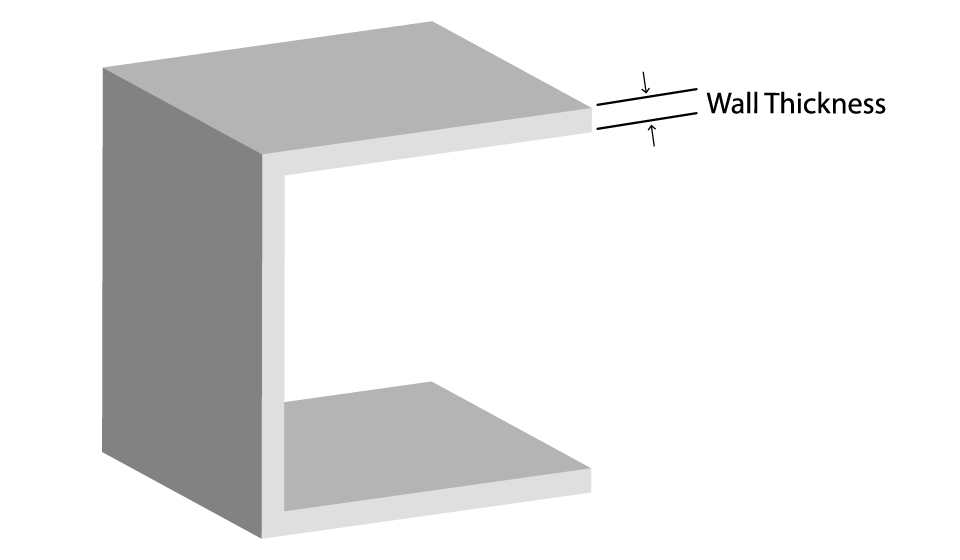
Wall Thickness
Specifications: .040″ mm – .075″ mm depending on material.
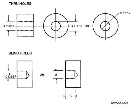
Hole Size
Specifications: Greater than .060″ diameter.
Escape Holes
Specifications: A minimum of .150″ mm diameter.
Text
Specifications: Minimum font height of .075″
Feature Size
Specifications: A minimum size of .040″
Embossed and Engraved Details
Specifications: Minimum depth of engraving & height of embossing .040″ & Minimum.
Tolerances
Specifications: ± 0.003″ per inch or ± 0.005″ overall whichever is greater.
|
Wall thickness – The minimum wall thickness to ensure a successful 3D print varies based on specific material between 0.7 mm (.030”) up to 2.0 mm (.075”) (for carbon or glass filled PA). |
|
Hole size – All holes should be a minimum of 1.5 mm (.060”) diameter to ensure material buildup inside the holes is kept to a minimum. Smaller holes can be designed in and printed, but expect to have to perform a post process of reaming them out to the correct diameter after the part is off the build. Orientation and placement of the holes relative to the CO2 laser should also be a consideration for high precision parts. Holes that are outside of the laser’s perpendicular reach may experienc overcure which causes the holes to come out oblong. |

|
Escape holes – To save weight (and sometimes costs) SLS parts can be printed hollowed out. To remove unsintered powder after production escape holes must be included. Escape holes must be a minimum of .015″ diameter. |
|
|
Feature size (pins, protruding features etc.) – A minimum size of 0.8 mm is recommended. |

|
Embossed and engraved details – To ensure small details are visible the following rules apply:
|
|
Tolerances – Typical tolerances for SLS parts are ± 0.3 mm or ± 0.05 mm/mm, whichever is greater. |
|
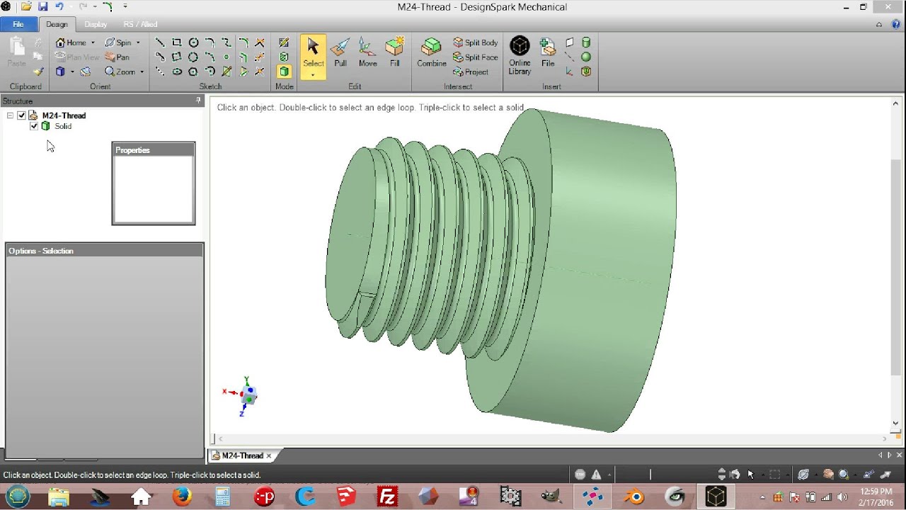
Threads The rough surface produced by SLS printing results in increased friction and can cause some issues when connecting threaded SLS parts together. It is possible to drill and tap SLS nylon. An ideal solution is only using SLS nylon for one of the threaded connections (either the hole or the bolt, not both). If the connection is critical to function of the part one of these methods for securing 3D printed parts should be considered. |

|
Living hinges SLS is one of the only 3D printing methods that can produce functional living hinges. For SLS hinges, anneal the hinge by heating it up (dipping in boiling water will often suffice) and then flexing the hinge back and forth. It is recommended living hinges are 0.3 – 0.8 mm thick and a minimum of 5 mm in length. |

|
Shrinkage – Most designs for SLS printing have overall dimensions increased by 3 – 3.5% at the pre-print analysis and conversion stage to accommodate shrinkage. This does not affect the design of a part. Warping – Large flat surfaces are most at risk. Consider adding ribs to increase stiffness. Part orientation during the printing stage can also help reduce the likelihood of warping. |

|
Material – There are a limited number of general purpose materials available in SLS that are all nylon based. Some are reinforced with glass fiber for increased rigitity, others offer flexibility but by and large the majority of SLS parts are built in traditional Nylon 12 or PA general purpose sintered powder |
*Table: Considerations: Tolerances, printer specs & limitations, and material properties.